In this post I'll guide you how to configure ports and simulate a demo LED blinking C code on Proteus and MPLAB simulator.


Port configuration function is done here

In the above written C code the first function to be executed is "SetupPorts()". In this function you can see that all pins of the port are made output. Writing a '0' to "TRISx" pin configures the pin as digital output. The next line clears any garbage data in "LATB" register. Control is then passed to an infinite loop which toggles the "LATB" register after every 500 milliseconds. Before we test the simulation in Proteus it is better to First test it in MPLAB SIM. Go to Debugger > Select Tool > MPLAB SIM.

MPLAB SIM is selected as debugger the next step is to set some global values. Go to Debugger > Settings. See figure below.

Once you are in debugger "Settings" the first thing to do is to change the oscillator value. See figure. Click "OK" to continue.

There are other settings too. For further details you have to read the documentation for MPLAB SIM available at www.microchip.com. I'll try to cover rest of the options in next posts.
We are now going to simulate and test the above written code in MPLAB SIM. For logic analysis of pin MPLAB SIM provides a tool called "Simulator Logic Analyzer". Here you can see the transition of signals and pin as you navigate through the code. To enable this option go to View > Simulator Logic Analyzer. The following window should appear.

You must add pins to see the transition going on to the pin here is how you add pins to this analyzer.

Select the desired pins and click add. For this chunk of code the associated port is PORTB. Select RB0 to RB7.

Click "OK" to continue. Pins added are being highlighted below.

The next step is to compile the code. Add a "Break Point" by double clicking at a specific code line.

Press "Play" button.

The code stops at the "Break Point". The following picture is a result of pressing "Play" button three to four times. See the transition against the pin.


You can find the source code and Proteus simulations from the following links.
https://dl.dropboxusercontent.com/u/77452173/PORTS/C%20Code.rar
https://dl.dropboxusercontent.com/u/77452173/PORTS/Proteus%20Simulation.rar
Video file is coming soon.
Reader comments are always welcomed. Thanks for reading.
I/O Ports:
Since I have chosen PIC18F252 microcontroller to work with one must know that it is a 28 pin high performance enhanced flash microcontroller. There are three bidirectional ports available with this microcontroller that are PORTA, PORTB and PORTC. Some pins of the I/O ports are multiplexed / shared with an alternate function from the peripheral features on the device. When a specific peripheral is enabled, that pin may not be used as a general purpose I/O pin. Each port pin is associated with three registers. These registers are:
- TRIS register (Controls the data direction)
- PORT register (Read voltages and logic level present at the pin)
- LAT register (Output latch register)
Configuring PORT as an Input / Output:
- Writing '1' to a specific bit of TRISx register configures the PORTx pin as an input.
- Writing '0' to a specific bit of TRISx register configures the PORTx pin as an output.
Schematics:
The basic Proteus schematics is shown below. This schematics is purely for code simulation and testing purposes only. The reason I am stating this is that most people say code running in Proteus does not work in real environment. Please note that the SPICE model of PIC18F252 in Proteus does not show the power and ground pins. They are internally attached to the VCC and VSS. Although there are pins available for the oscillator but you still need to define oscillator frequency in proteus. To do this you need to double click the IC and set oscillator frequency in clock section. If you want to make your hardware work in real environment one must follow the basic circuitry given in PIC18F252 datasheet.
LED Blinking Code:
The main application function is shown below
Port configuration function is done here
In the above written C code the first function to be executed is "SetupPorts()". In this function you can see that all pins of the port are made output. Writing a '0' to "TRISx" pin configures the pin as digital output. The next line clears any garbage data in "LATB" register. Control is then passed to an infinite loop which toggles the "LATB" register after every 500 milliseconds. Before we test the simulation in Proteus it is better to First test it in MPLAB SIM. Go to Debugger > Select Tool > MPLAB SIM.
MPLAB SIM is selected as debugger the next step is to set some global values. Go to Debugger > Settings. See figure below.
Once you are in debugger "Settings" the first thing to do is to change the oscillator value. See figure. Click "OK" to continue.
There are other settings too. For further details you have to read the documentation for MPLAB SIM available at www.microchip.com. I'll try to cover rest of the options in next posts.
You must add pins to see the transition going on to the pin here is how you add pins to this analyzer.
Select the desired pins and click add. For this chunk of code the associated port is PORTB. Select RB0 to RB7.
Click "OK" to continue. Pins added are being highlighted below.
The next step is to compile the code. Add a "Break Point" by double clicking at a specific code line.
Press "Play" button.
The code stops at the "Break Point". The following picture is a result of pressing "Play" button three to four times. See the transition against the pin.
There is lot more to discover in "Logic Analyzer". From my point of view it is a virtual oscilloscope in one's hand. You can probe each and every peripheral of PIC devices using this feature. Further details and information can be found at http://www.cis.upenn.edu/~lee/06cse480/data/MPLAB_IDE_User_guide.pdf and http://nnp.ucsd.edu/phy120b/pic_manuals_pdf/mplab_simu_edit_user.pdf.
Tracing code:
Lets say that you have written a code that has included many files and after some time you need to edit some function or you forgot where it is written. Here is a method which lets you keep track of your functions and data types.
In the above chunk of code lets trace "DelayBigUs(100);" function. Right click on the function and you will see a number of option available. Once you right click some function, struct member or data type you will see the following.
Click "Go to Locator" it will automatically take you to the file where the code was written. Doing this IDE took me to the required file and it seems some thing like this.

Note that the code pointer is pointing to "line 18".
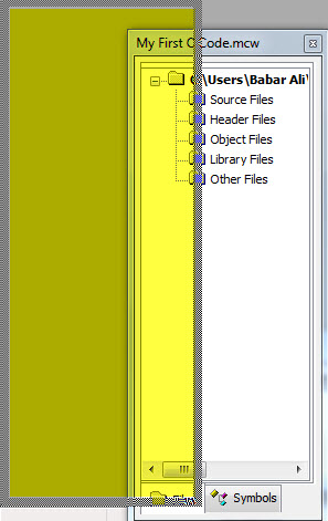
Some time doing the above thing do not take effect. To solve this you have to click the "Symbol" tab see below.
Right click in the the empty space and select "Update Tags now".
Click the file tab next to symbols. Look for the function/struct member to trace and follow the procedure explained above for tracing functions.
https://dl.dropboxusercontent.com/u/77452173/PORTS/C%20Code.rar
https://dl.dropboxusercontent.com/u/77452173/PORTS/Proteus%20Simulation.rar
Video file is coming soon.
Reader comments are always welcomed. Thanks for reading.